The SZJ-AT-1 Reed Switch Tester is developed with a single-chip microcomputer for testing the reed switch's pull-in and release AT values ​​(or pull-in and release current), pull-in and release AT-value differences (or current differences). ) Intelligent test instrument for contact resistance of contacts. Each parameter is set by the dial on the panel. When the power is turned off, the set parameters will not be lost. When the number of turns of the set coil is zero, the pull-in current and the release current value of the reed switch or relay are tested.
(three). Operating instructions
1. Parameter setting:
Connect the 15-pin cable to the relay socket or the reed switch coil according to the wiring diagram. There are seven sets of DIP switches on the panel, which are the upper limit of suction, the lower limit of suction, the upper limit of release, the lower limit of release, the difference of AT value, the contact resistance and the number of turns. Note that the number of turns is only two digits, the number dialed should be multiplied by 100; when the set number of turns is a non-zero value, the pull-in, release, and difference are all AT values. When the number of turns is set to zero, the pull-in, release, and difference are current values. Contact resistance is not affected by it. When the set parameter is AT value, the upper and lower limit dial values ​​have two decimal places, the maximum is 99.99, the difference has one decimal place or when the set parameter is the current value, the upper and lower limit dial values The last two digits are decimals, the maximum is 19.99 mA (this bit is invalid when the highest bit > 1), the difference is only one decimal place, and the current unit is mA. The unit of contact resistance is mΩ.
2. Coil drive voltage selection:
The panel has a "coil rated voltage" toggle switch that can select a 6V or 12V coil drive voltage.
3. Product type selection:
There is a “contact type†band switch on the panel. When the product under test is normally open (type A), the band switch is switched to the A position; when the product under test is normally closed (type B), the band switch is switched to B file; when the product under test is a conversion type (C type), the band switch is set to the C position.
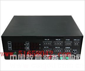
4. When all the parameters are set, turn on the power switch. At this time, the instrument panel display shows: the first screen displays “SZJ-AT-1â€; the second screen displays: the upper limit of suction, the lower limit of suction, the difference between AT and Contact resistance; the third screen displays: upper release limit, lower release limit, coil voltage and number of turns. Displaying these data verifies that the parameters set are correct and that all switches are in good contact.
5. When the power is found to be incorrectly set, you can reset it and modify the inappropriate parameters. Attention! After the parameters are modified, you must press the reset button or re-open the power supply, and the tester will confirm the new parameters.
6. After the parameters are set, you can press the test button to test. After the test, the test results are displayed. If the qualified PASS light is on, otherwise the FAIL light is on. Attention! The upper limit of the suction should be set above the actual suction value of the normal product, otherwise it will affect the test results.
(4) SZJ-SZJ-AT-1 reed switch AT value tester debugging manual
Check the power supply voltage before debugging: 5V, 12V, -12V, 3V, see if it is correct: the following is the general value,
5V: 4.85---5.25V; 12V: 11.4---12.6V
-12V: -11.4-- -12.6V ; 3V: 1.8-3V
If it is not within the scope, find out the cause and repair it. After it is correct, connect it to the tester.
(A). Voltage debugging:
1) Adjust the reference voltage:
Adjust W3 to make TP1 voltage -5.12 V, and adjust W2 to make TP2 0.00V;
2) Then set the AT difference to 999, the contact resistance to 999, and the number of turns to 00. Select the coil voltage to be 12V. Press the reset button to see if the displayed data is correct. If it is correct, press the test button again, the digital tube displays “12Vâ€. At this time, adjust W2 to make TP2 5V.
3) The coil voltage should be 12V at this time. If not, check if the resistor R12 (90K) R13 (10K) is soldered incorrectly, and adjust RW5 to make it within the range.
(two). Current debugging:
After the above operation, set the upper limit of the pull-in current (≤19.99mA) and the upper limit of the release current (≤19.99mA). Disconnect the tested relay coil; press the reset button to see if the displayed number is correct. Then press the test button to display the voltage, then press the test button to display the upper limit of the pull-in current. Adjust the 50Ω potentiometer (next to the relay K16). The output of the coil makes the output current the display value.
(three). Adjust the contact resistance
Press the reset button to adjust W6 so that the current of TP3 to ground is 10 mA. The contact resistance zero point is completed by adjusting RW4. Connect the standard milliohm resistance (according to the four-wire connection method), test in the normal way, read the test results, and repeatedly adjust RW6 and RW4 so that the test value and the actual value are within the entire range.
Shenzhen Nanfang Shishang Cosmetic Utensil Co., Ltd. , https://www.sznfssmakeupbrush.com