With the rapid development of electronic technology, the control system based on single-chip microcomputer has been widely used in industries such as industry, agriculture, electric power, electronics, intelligent buildings, etc. As the main body and core of embedded control system, microcomputer replaces the conventional control system. Electronic circuit. The development and maturity of building intelligence has also laid a solid foundation for the popularization and application of single-chip based lighting control systems. This paper introduces the indoor lighting control system based on single-chip AT89C51 and its principle, and proposes an effective energy-saving control method. The system uses the more mature sensing technology and computer control technology, and uses multiple parameters to control the indoor lighting of the school classroom. The system is composed of a single-chip microcomputer and a variety of interface circuits. There are six main parts: AT89C51 chip, optical signal acquisition circuit, human body signal acquisition circuit, clock control circuit DS12887, output control circuit and timing monitor circuit.

Main controller circuit design
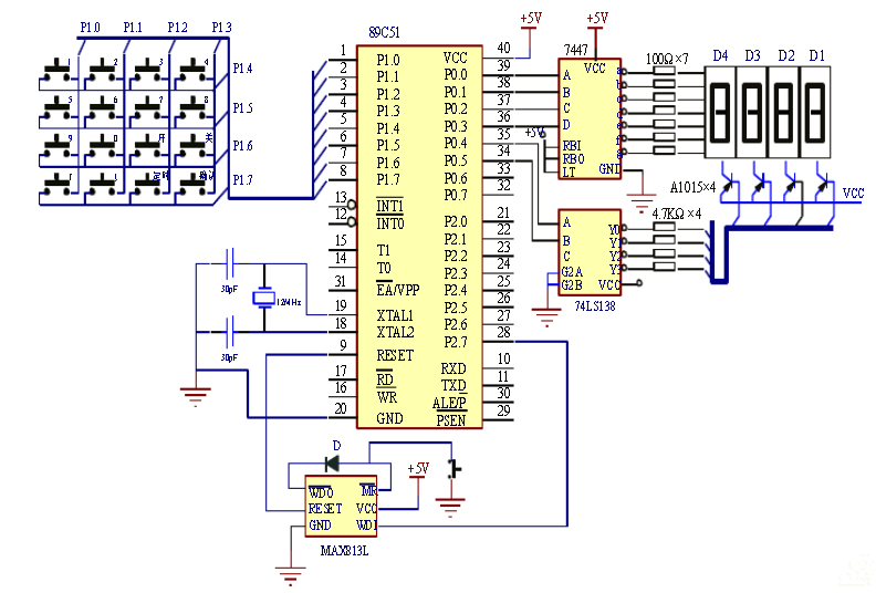
The main controller adopts AT89C51 single-chip microcomputer as the microprocessor. AT89C51 is a low-voltage, high-performance CMOS 8-bit single-chip microcomputer produced by American ATMEL Company. The chip contains 4K bytes of re-writable Flash read-only program memory and 128 bytes of random memory. Take data memory (RAM), the device is produced by ATMEL's high-density, non-volatile memory technology, compatible with the standard MCS-51 command system, built-in general-purpose 8-bit central processing unit (CPU) and flash memory unit. The peripheral interface circuit of the main controller system is composed of a keyboard, a digital display and a driving circuit, a crystal oscillator, a watchdog circuit, and a communication interface circuit. The hardware circuit schematic of the main controller system is shown in Figure 1.

Figure 1 Schematic diagram of the hardware circuit of the main controller system
Design of RS485 communication circuit
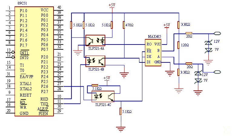
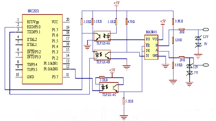
In various distributed distributed control systems, one single-chip microcomputer is often used as the host, and multiple single-chip microcomputers are used as slaves. The host controls the operation of the whole system; the slaves collect signals to realize on-site control; the master and slave are connected by bus. , as shown in Figure 2-4. The host sends information to each slave (point to point) or multiple slaves (broadcast) through TXD, and each slave can also send information to the host, but the slaves cannot communicate freely, and they must transmit information through the host. .
The wired communication mode of the system uses RS485 bus for communication, and the RS485 standard supports half-duplex communication. It only needs three lines to transmit and receive data, and has the ability to suppress common mode interference. The receiving sensitivity can reach ±200mV. The communication distance is increased, and the communication distance can reach 1200m at 100K bps. If the communication distance is shortened, the maximum rate can reach 10M bps. The master-slave communication method is used here, the host is operated by the master controller, and the slave is the sub-controller. The master is in a dominant and dominant position. The slave receives and transmits data in an interrupted manner. The information sent by the master can be transmitted to all slaves or specified slaves. The information sent by the slave can only be received by the master. Direct communication. The communication circuit diagrams of the master and the slave are shown in Figure 2 and Figure 3, respectively.

Figure 2 host communication circuit diagram
Slave communication and optical signal sampling circuit design
The RS485 communication transceiver chip selected by the master and the slave is MAX485. It is a low-power transceiver device for RS485 communication produced by MAXIM. It uses a single power supply +5 V operation, rated current is 300 μA, and adopts half-duplex communication mode. . It performs the function of converting the TTL level to the RS485 level. The MAX485 chip contains a driver and receiver inside. The RO and DI terminals are the output of the receiver and the input of the driver respectively. When connected to the MCU, only need to be connected to the RXD and TXD of the MCU respectively; the RE and DE terminals are the enable and receive ends respectively, and the RE end When it is logic 0, the device is in the receiving state; when the DE terminal is logic 1, the device is in the transmitting state. Because MAX485 works in the half-duplex state, it is only necessary to control these two pins with one pin of the single-chip microcomputer. The master and the slave use the P2.6 and P1.0 pins respectively to control; the A and B terminals are the differential signal terminals for receiving and transmitting respectively. When the level of the A pin is higher than B, the data sent by the representative is 1 When the level of A is lower than the B terminal, it means that the transmitted data is 0. Only one signal is needed to control the reception and transmission of the MAX485 during communication. At the same time, a matching resistor is added between the A and B terminals, and a 120Ω resistor is used here.

Figure 3 slave communication circuit diagram
In order to improve the anti-interference ability of the system, the communication system is optically isolated by the photocoupler TLP521. The slave uses the P1.0 of the single-chip microcomputer to control the working state of the communication transceiver MAX485, and normally sets P1.0 to the low level, so that the slave serial port is in the listening state. When there is a serial interrupt, it is judged whether it is the local number. If it is the local address, set P1.0 to high level, send the response message, and then set P1.0 to the low level to receive the control command, and continue to maintain P1. .0 is low, so that the serial transceiver is in the receiving state; if it is not the local address, make P1.0 low, so that the serial transceiver is in the receiving and listening state.
Optical signal sampling circuit
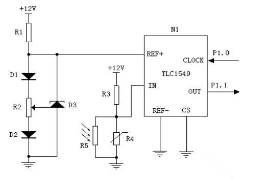
The optical signal sampling circuit is shown in Figure 4. The figure is mainly composed of an optical signal acquisition circuit and an A/D analog-to-digital conversion circuit, wherein analog-to-digital conversion is the core of the circuit. The signal is sent to the A/D conversion circuit after being collected, and processed by the single-chip microcomputer, and finally used as the basis for the system application to determine the switching light. The number of bits in the A/D converter should be chosen according to the measurement range and accuracy of the signal, so that it has sufficient data length to ensure that the maximum quantization error is within the accuracy required by the design. In this system, the voltage of the measurement range of the signal is 0.00-9.99V and the accuracy is 0.01V. In this design, the 10-bit analog-to-digital converter TLC1549 with serial control, which is produced by Texas Instruments (TI), uses CMOS technology with automatic sampling and hold, using differential reference. High-impedance input voltage, good anti-interference performance, can be calibrated by proportional range, and the total unadjustable error is (±)1LSB Max, and the chip is small. At the same time, it adopts Microwire serial interface mode, so there are few pins and the interface is convenient and flexible. Compared with the traditional parallel mode interface A/D converter (such as ADC0809/0808), the interface circuit of the single chip microcomputer is simple, and the I/O port resource is small.

Figure 4 optical signal sampling circuit
This paper is based on the design principle and implementation method of intelligent lighting control system of AT89C2051 single chip microcomputer. First, according to the design requirements, use Protel DXP software to draw the schematic diagram, then select the components according to the schematic diagram, arrange the components on the experiment board and connect the lines, test the hardware circuit, check whether the serial port is wrong, and measure whether the power supply is normal. Whether the reset level is correct, whether the microcontroller starts up, and so on. Since this design is designed in a relatively ideal situation, in practical applications, the lighting control system and the projection equipment power supply need to be separated. When applied to other workplaces, some modules can be added or reduced according to actual needs. For example, when the road is used, no time control circuit is needed; when used indoors, a wireless module can also be added to facilitate control.
The book cover is the outermost layer of the book, including A4,A5,B5 and other sizes.The cover can protect the book from damage and has an aesthetic effect.Our company's book covers are made of PP and PVC, with exquisite patterns and solid quality, supporting customized LOGO.The book cover has a small pocket with a built-in information card. It is suitable for school students to use.
Plastic Book Cover,Book Cover,Pvc Book Cover,Printed Book Cover
shaoxing chaofeng stationery manufacturing CO.,LTD. , https://www.chaofengstationery.com